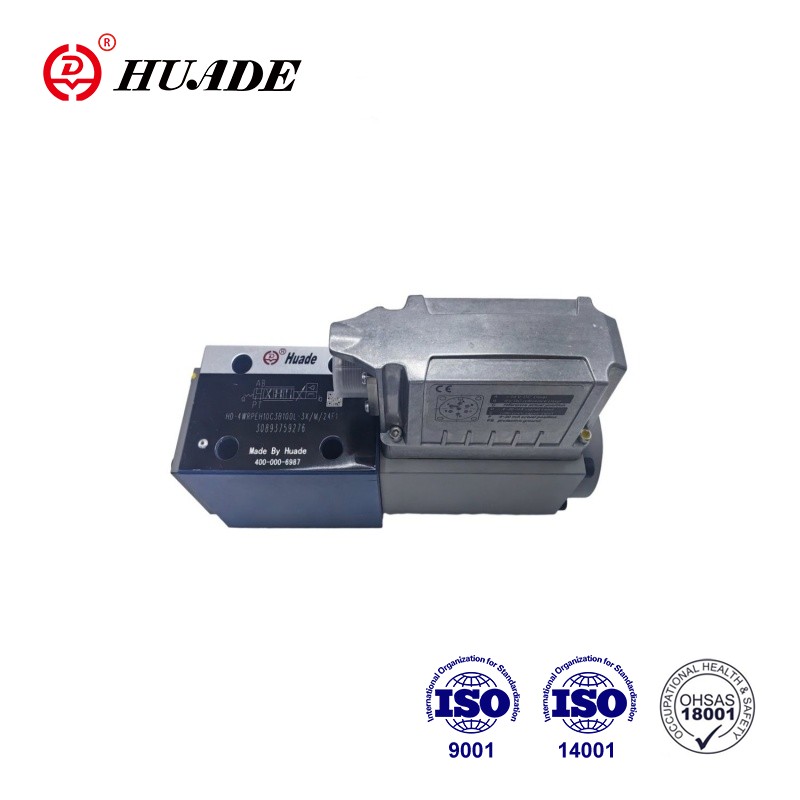
Valves of type 4WRPEH 6-3X are direct operated directional control valves with electrical position feedback and integrated electronics (OBE). Proportional directional servo valve 4WRPEH 6-3X is a high-precision control valve that combines proportional technology with servo technology. 4WRPEH 6-3X is widely used in various process flows and equipment operations, such as hydraulic systems in the petroleum, chemical, metallurgical and other industries to control various process flows and equipment operations.
Proportional Directional Servo Valve 4WRPEH 6-3X
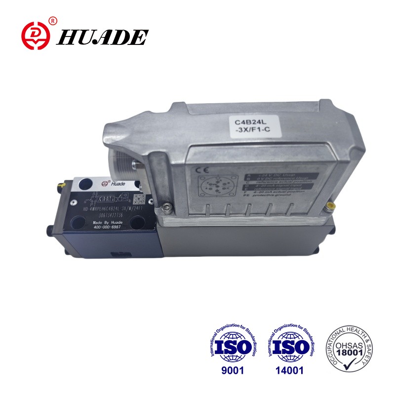
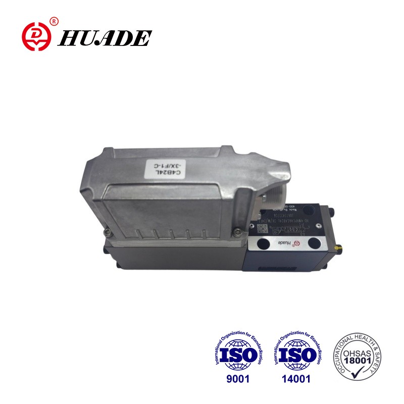
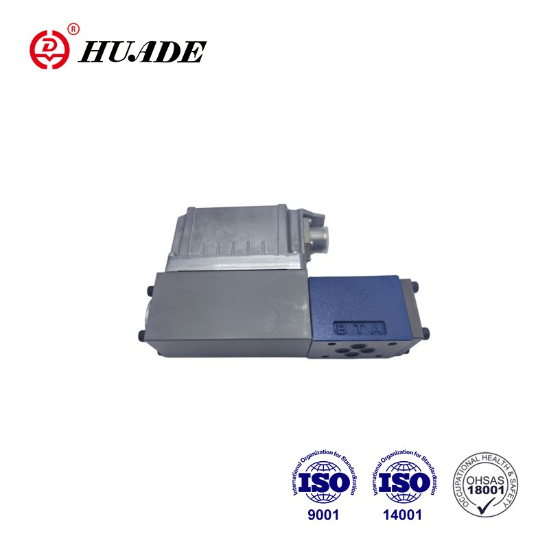
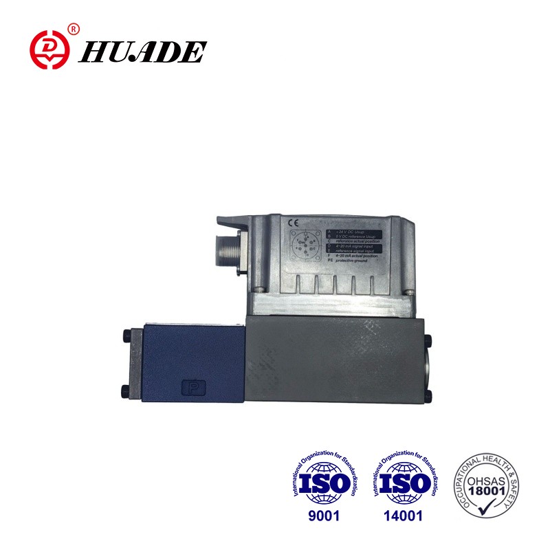
TECHNICAL REPLACEMENT NOTICE
This Huade® directional control valve serves as a 100% direct drop-in replacement for Bosch Rexroth PROPORTIONAL-DIRECTIONAL-SERVO-VALVE-4WRPEH-6-3X equivalents. Dimensions, mounting interfaces, and technical parameters are identical. Designed for cost reduction in industrial and mobile hydraulic systems.
• Product features:Safe ,Energy-effcient
• Specifications: 4WRPEH 6-3X series,
• Applications:engineering machinery, aerospace, shipbuilding
Request B2B Quote
Submit your target quantity and technical questions. Our hydraulic engineering team will provide a factory-direct quote and lead time estimate within 24 hours.
Send Product Inquiry Download PDF Datasheet
✓
100% Genuine Huade
Direct factory authorized supply
✓
ISO 4401 Mounting
ISO 4401 / Rexroth interchangeable
✓
Secure Packaging
Sealed rust-proof global shipping
Technical Data Sheet
- Product Overview
- Features & Applications
- Technical Parameters
Product Overview
Key Features
- Reliable - proven and robust design
- Safe - fail-safe position of the control spool in switched-off condition
- Energy-effcient - no pilot oil demand
- High quality - control spool and sleeve in servo quality
- Flexible - suitable for position, velocity and pressure control
- Precise - high response sensitivity and little hysteresis
- IO-Link interface, optional. Use of the valve with IO-Link as a shut-off element up to category 3, PL d according to EN 13849-1.
Industrial Applications
- Proportional directional servo valve 4WRPEH 6-3X is widely used in the field of industrial automation,wind turbines, machine tool control, engineering machinery, aerospace, shipbuilding and marine engineering.
- Set-up
- The HD-4WRPEH high-response valve mainly consists of:
- Valve housing with control spool and sleeve in servo quality (1)
- Control solenoid with position transducer (2)
- (optionally with electronics protection membrane (5))
- On-board electronics (OBE) (3) with analog or IO-Link interface (4) (optionally with damping
- plate (6))
- Function
- The integrated electronics (OBE) compares the specified command value to the position actual value. In case of control deviations, the stroke solenoid will be activated. Due to the changed solenoid force, the control spool is adjusted against the spring. Stroke/control spool cross-section is controlled proportionally to the command value. In case of a command value presetting of 0, the electronics adjusts the control spool against the spring to central position. In deactivated condition, the spring is untensioned to a maximum and the valve is in fail-safe position.
- Safety function (IO-Link shut-off)
- By shutting off the supply voltage at the IO-Link master (Class B-Port), pins 2 and 5, the IO-Link valve can be safely switched off. After shut-off of the supply voltage, the control spool of the valve is set to fail-safe position. In order to also guarantee the hydraulic prerequisite for the safety shut-down, the overlap of control spool/sleeve must also be considered.
- Sufficient overlap is guaranteed by the symbols C3, C5, C4 and C1.
- The safe shut-off is not part of the IO-Link valve and must be taken into account for the safe design of the machinery.
- Control solenoid shut-off
- In case of the following errors, the control solenoids are de-energized by the integrated electronics (OBE) and the control spool is set to fail-safe position:
- Falling below the minimum supply voltage
- Only at interface "F1":
- – Falling below the minimum current command value of 2 mA (includes cable break of the command value line (current loop))
- Only at interface "L1":
- – Enable inactive, communication interruption (watchdog)
- – In case of internal IO-Link error
- Only at interface "C6":
- – Additionally, release inactive
- Damping plate "D"
- The damping plate reduces the acceleration amplitudes on the on-board electronics (frequencies >300 Hz).
- Notice:
- Use of the damping plate is not recommended for applications with mainly low-frequency excitation
- Electronics protection membrane "-967"
- To prevent condensate formation in the housing of the integrated electronics (OBE), an electronics protection membrane (5) can be used.
- Recommended for use outside industry-standard conditions with high ambient air humidity and significant cyclic temperature changes (e.g. outdoors).
- Symbols of Proportional Directional Servo Valve 4WRPEH 6-3X
Technical Parameters
Mechanical ratings and operating limits for the Proportional Directional Servo Valve 4WRPEH 6-3X:
| Parameter / Dimension Name | Value / Rating Specification |
|---|---|
| Technical data | Technical data |
| General | General |
| Type of connection | Subplate mounting |
| Porting pattern | ISO 4401-03-02-0-05 |
| Weight (kg) | 2.9 |
| Installation position | Any |
| Ambient temperature range (°C) | –20 … +60 |
| Transport temperature(°C) | –30 … +80 |
| Maximum storage time (Years) | 1 |
| Maximum relative humidity (no condensation) (%) | 95 |
| Protection class according to EN 60529 | IP65 (if suitable and correctly mounted mating connectors are used) |
| Maximum surface temperature (°C) | 150 |
| MTTFD value according to EN ISO 13849 (Years) | 150 (for further details see data sheet 08012) |
| Sine test according to DIN EN 60068-2-6 - Without damping plate | 10 ... 2000 Hz / maximum of 10 g / 10 cycles / 3 axes |
| Sine test according to DIN EN 60068-2-6 - With damping plate 1) | 10 ... 2000 Hz / maximum of 10 g / 10 cycles / 3 axes |
| Noise test according to DIN EN 60068-2-64 - Without damping plate | 20 … 2000 Hz / 10 gRMS / 30 g peak / 30 min. / 3 axes |
| Noise test according to DIN EN 60068-2-64 - With damping plate 1) | 20 ... 2000 Hz / 10 gRMS / 30 g peak / 24 h / 3 axes |
| Transport shock according to DIN EN 60068-2-27 - Without damping plate | 15 g / 11 ms / 3 shocks / 3 axes |
| Transport shock according to DIN EN 60068-2-27 - With damping plate 1) | 15 g / 11 ms / 3 shocks / 3 axes |
| Shock according to DIN EN 60068-2-27 - With damping plate 1) | 35 g / 6 ms / 1000 shocks / 3 axes |
| Conformity - CE according to EMC directive 2014/30/EU, tested according to | EN 61000-6-2 and EN 61000-6-3 |
| Conformity - RoHS directive | 2011/65/EU |